|
|
|
Finite element modeling of counter-roller spinning for large-sized aluminum alloy cylindrical parts |
Dawei ZHANG( ), Fan LI, Shuaipeng LI, Shengdun ZHAO ), Fan LI, Shuaipeng LI, Shengdun ZHAO |
| School of Mechanical Engineering, Xi’an Jiaotong University, Xi’an 710049, China |
|
|
|
|
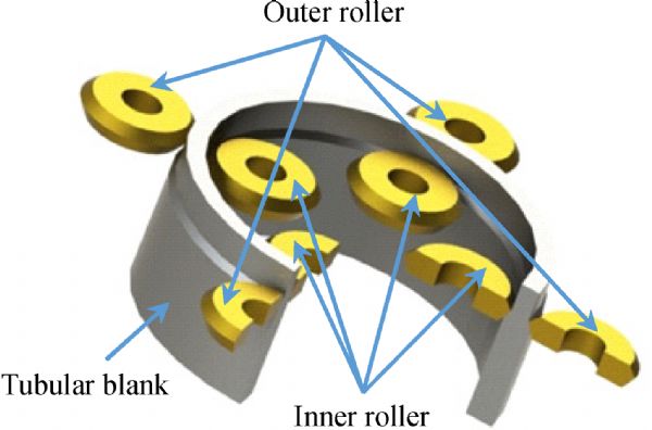
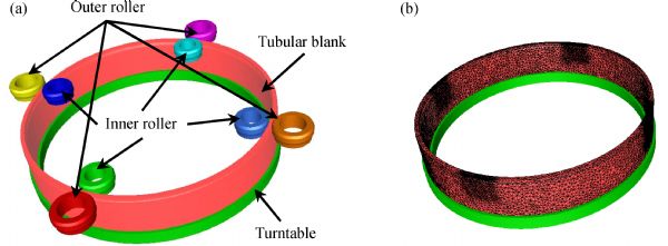
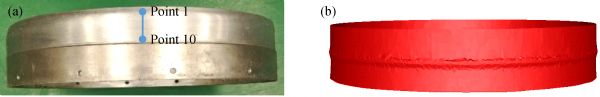
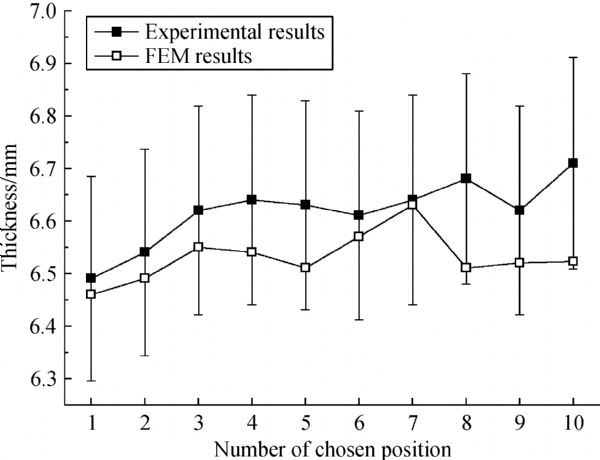
Abstract Counter-roller spinning (CRS), where the mandrel is replaced by rollers, is an effective means of manufacturing large-sized, thin-walled, cylindrical parts with more than 2500 mm diameter. CRS is very complex because of multi-axis rotation, multi-local loading along the circumference, and radial-axial compound deformation. Analytical or experimental methods cannot fully understand CRS. Meanwhile, numerical simulation is an adequate approach to investigate CRS with comprehensive understanding and a low cost. Thus, a finite element (FE) model of CRS was developed with the FORGE code via meshing technology, material modeling, determining the friction condition, and so on. The local fine mesh moving with the roller is one of highlights of the model. The developed 3D-FE model was validated through a CRS experiment by using a tubular blank with a 720 mm outer diameter. The developed 3D-FE model of CRS can provide a basis for parameter optimization, process control, die design, and so on. The data on force and energy predicted by the 3D-FE model can offer reasonable suggestions for determining the main mechanical parameters of CRS machines and selecting the motors. With the predicted data, an all-electric servo-drive system/machine with distributed power was designed in this work for CRS with four pairs of rollers to manufacture a large-sized, thin-walled, cylindrical part with 6000 mm diameter.
|
| Keywords
large-sized cylindrical part
counter-roller spinning
aluminum alloy
finite element method
distributed power
|
|
Corresponding Author(s):
Dawei ZHANG
|
|
Just Accepted Date: 20 November 2018
Online First Date: 21 December 2018
Issue Date: 24 July 2019
|
|
| 1 |
C C Wong, T A Dean, J Lin. A review of spinning, shear forming and flow forming process. International Journal of Machine Tools & Manufacture, 2003, 43(14): 1419–1435
https://doi.org/10.1016/S0890-6955(03)00172-X
|
| 2 |
Q X Xia, G F Xiao, H Long, et al. A review of process advancement of novel metal spinning. International Journal of Machine Tools & Manufacture, 2014, 85: 100–121
https://doi.org/10.1016/j.ijmachtools.2014.05.005
|
| 3 |
M Zhan, H Yang, J Guo, et al. Review on hot spinning for difficult-to-deform lightweight metals. Transactions of Nonferrous Metals Society of China, 2015, 25(6): 1732–1743
https://doi.org/10.1016/S1003-6326(15)63778-5
|
| 4 |
F Ma, H Yang, M Zhan. Plastic deformation behaviors and their application in power spinning process of conical parts with transverse inner rib. Journal of Materials Processing Technology, 2010, 210(1): 180–189
https://doi.org/10.1016/j.jmatprotec.2009.07.006
|
| 5 |
M Zhan, J Guo, M W Fu, et al. Formation mechanism and control of flaring in forward tube spinning. International Journal of Advanced Manufacturing Technology, 2018, 94(1–4): 59–72
https://doi.org/10.1007/s00170-017-0690-6
|
| 6 |
J H Zhang, M Zhan, H Yang, et al. 3D-FE modeling for power spinning of large ellipsoidal heads with variable thicknesses. Computational Materials Science, 2012, 53(1): 303–313
https://doi.org/10.1016/j.commatsci.2011.08.010
|
| 7 |
X W Cao, L W Zhang, Y T Yang, et al. Progress of research on counter-roller forming. Hot Working Technology, 2013, 42(9): 115–117 (in Chinese)
|
| 8 |
X Y Zhou. Counter-roller spinning: A new process for manufacturing large tube with high strength and precision. Forging & Stamping Technology, 1993, 18(2): 49–51 (in Chinese)
|
| 9 |
G F Xiao, Q X Xia, X Q Cheng, et al. Research on the grain refinement method of cylindrical parts. International Journal of Advanced Manufacturing Technology, 2015, 78(5‒8): 971–979
https://doi.org/10.1007/s00170-014-6686-6
|
| 10 |
H Grönert, M Eckert, H von Petersdorff, et al. US Patent, 4766752, 1988-08-30
|
| 11 |
H Grönert, M Eckert. US Patent, 4951490, 1990-08-28
|
| 12 |
H Yang, M Zhan, Y L Liu, et al. Some advanced plastic processing technologies and their numerical simulation. Journal of Materials Processing Technology, 2004, 151(1–3): 63–69
https://doi.org/10.1016/j.jmatprotec.2004.04.015
|
| 13 |
D W Zhang, H Yang, Z C Sun. 3D-FE modelling and simulation of multi-way loading process for multi-ported valve. Steel Research International, 2010, 81(3): 210–215
https://doi.org/10.1002/srin.200900110
|
| 14 |
D W Zhang, S D Zhao. Numerical study on forming complex fitting body on end of integrated stainless steel pipe without welds. Journal of Central South University, 2016, 23(2): 269–276
https://doi.org/10.1007/s11771-016-3070-8
|
| 15 |
D W Zhang, S D Zhao, H Yang. Analysis of deformation characteristic in multi-way loading forming process of aluminum alloy cross valve based on finite element model. Transactions of Nonferrous Metals Society of China, 2014, 24(1): 199–207
https://doi.org/10.1016/S1003-6326(14)63048-X
|
| 16 |
Z Y Xiao, T Zhang. Rigid-plastic finite element analysis of opposite roller spinning. Forging & Stamping Technology, 1999, 24(1): 27–30 (in Chinese)
|
| 17 |
G F Xiao, Q X Xia, X Q Cheng, et al. Metal flow model of cylindrical parts by counter-roller spinning. Procedia Engineering, 2014, 81: 2397–2402
https://doi.org/10.1016/j.proeng.2014.10.340
|
| 18 |
Q H Xi, W X Fan, W Lv, et al. Orthogonal test of counter roller spinning by numerical simulation. Forging & Stamping Technology, 2016, 41(8): 154–158 (in Chinese)
|
| 19 |
D B Shan, Y Q Zhang, Y Wang, et al. Defect analysis of complex-shape aluminum alloy forging. Transactions of Nonferrous Metals Society of China, 2006, 16(S3): 1574–1579
|
| 20 |
M He, F G Li, Z G Wang. Forming limit stress diagram prediction of aluminum alloy 5052 based on GTN model parameters determined by in situ tensile test. Chinese Journal of Aeronautics, 2011, 24(3): 378–386
https://doi.org/10.1016/S1000-9361(11)60045-9
|
| 21 |
X X Wang, M Zhan, J Guo, et al. Evaluating the applicability of GTN damage model in forward tube spinning of aluminum alloy. Metals, 2016, 6(6): 136
https://doi.org/10.3390/met6060136
|
| 22 |
T Altan, S I Oh, H L Gegel. Metal Forming: Fundamentals and Application. Metal Park: American Society for Metals, 1983
|
| 23 |
D W Zhang, H Yang, H W Li, et al. Friction factor evaluation by FEM and experiment for TA15 titanium alloy in isothermal forming process. International Journal of Advanced Manufacturing Technology, 2012, 60(5–8): 527–536
https://doi.org/10.1007/s00170-011-3624-8
|
| 24 |
D W Zhang, H Ou. Relationship between friction parameters in Coulomb-Tresca friction model for bulk metal forming. Tribology International, 2016, 95: 13–18
https://doi.org/10.1016/j.triboint.2015.10.030
|
| 25 |
D W Zhang, M C Cui, M Cao, et al. Determination of friction conditions in cold-rolling process of shaft part by using incremental ring compression test. International Journal of Advanced Manufacturing Technology, 2017, 91(9–12): 3823–3831
https://doi.org/10.1007/s00170-017-0087-6
|
|
Viewed |
|
|
|
Full text
|
|
|
|
|
Abstract
|
|
|
|
|
Cited |
|
|
|
|
| |
Shared |
|
|
|
|
| |
Discussed |
|
|
|
|