|
|
|
Assessment of an alternative to deep foundations in compressible clays: the structural cell foundation |
Sergio A. MARTÍNEZ-GALVÁN( ), Miguel P. ROMO ), Miguel P. ROMO |
| Institute of Engineering, National University of Mexico, Mexico City 04510, Mexico |
|
|
|
|
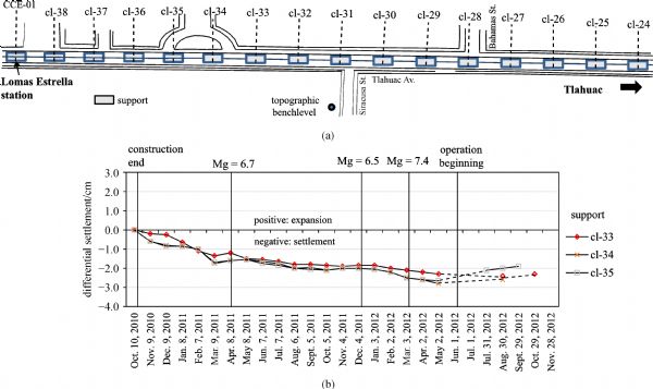
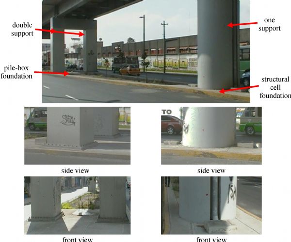
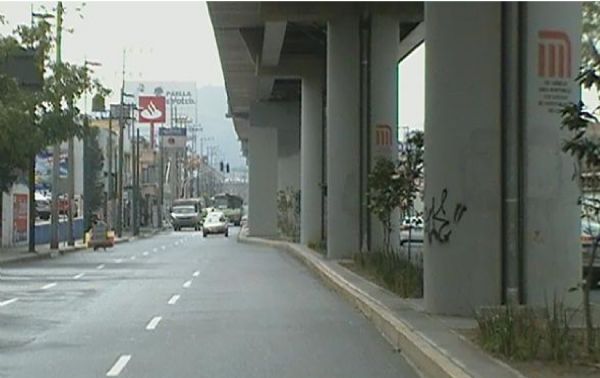
Abstract The new type of deep foundation for buildings on saturated, compressible-low strength clayey soil deposits, branded structural cell essentially consists of a rigid concrete top slab, structurally connected to reinforced concrete peripheral walls (diaphragms) that enclose the natural soil. Accordingly, as the initial volume of the confined soft clays within the lateral stiff diaphragms will remain constant upon loading, the hollowed structural cell will be “transformed” into a very large cross-section pillar of unit weight slightly higher than that of the natural soft clayey soil. This type of foundation seems to be a highly competitive alternative to the friction pile-box foundations (widely used in Mexico City clays), due to its economic and environmental advantages. Economies result, for example, from the absence of huge excavations hence sparing the need of earth retaining structures. Further savings result from appreciably smaller concrete volumes required for building the structural cell than the friction pile-box foundation; moreover, the construction time of the former is much shorter than that of the latter. Regarding the impact to the environment, less air contamination follows from the fact that both traffic jams and soil excavation lessen appreciably. Considering these facts and others regarding scheduling, it was decided to replace 48-friction pile-box foundations specified in the master plan project by this new type of foundation. The overall behavior of these cell foundations over a five-year period is fared from close visual observations and their leveling during the first three years after their construction.
|
| Keywords
deep foundations
bearing capacity
resistant moment
structural cell
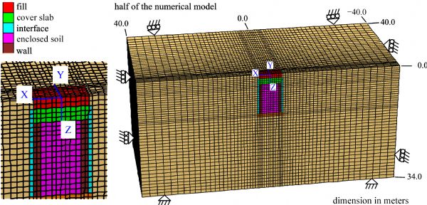
3D numerical modeling
|
|
Corresponding Author(s):
Sergio A. MARTÍNEZ-GALVÁN
|
|
Online First Date: 16 June 2017
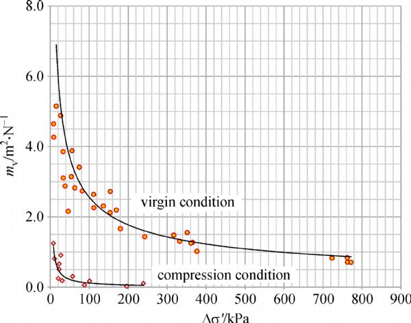
Issue Date: 08 March 2018
|
|
| 1 |
Cheng Q, Wu J, Song Z, Wen H. The behavior of a rectangular closed diaphragm wall when used as a bridge foundation. Front. Struct. Civ. Eng., 2012, 6(4): 398–420
https://doi.org/10.1007/s11709-012-0175-5
|
| 2 |
Martin C M. Vertical bearing capacity of skirted circular foundations on Tresca soil. In: Proc. 15th Int. Conf. on Soil Mechanics and Geotechnical Engineering, Istanbul, 2001, 743–746
|
| 3 |
Brasby M F, Randolph M F. The effect of skirted foundation shape on response to combined V-M-H loadings. International Journal of Offshore and Polar Engineering, 1999, 9(5): 987–995
|
| 4 |
Bransby M F, Randolph M F. Combined loading of skirted foundation. Geotechnique, 1998, 48(5): 637–655
https://doi.org/10.1680/geot.1998.48.5.637
|
| 5 |
Saito T, Yoshida Y, Itoh M, Masui N. Skirt suction foundation–application to strait crossings.
|
| 6 |
Martínez-Galván S A. Simplified analysis method for a new type of foundation in soft soils. PhD thesis in engineering, National University of Mexico, Mexico, 2012, 135 (in Spanish)
|
| 7 |
Takaya K. Box-shaped rigid base for continuous underground wall. Journal of Civil Engineering, 1980, 65(4): 35–42 (in Japanese)
|
| 8 |
Katsuhiro A, Takahashi Y, Ogasawara L. Basic railway bridge design example: a wall with continuous rigid base. Foundation Work, 1982, 10(12): 70–77 (in Japanese)
|
| 9 |
Smoltczyk U. Geotechnical Engineering Handbook Volume 3: Elements and Structures. Berlin: Ernst&Sohn, 2003
|
| 10 |
Wong I H. Experience with waterproofness of basements constructed of concrete diaphragm walls in Singapore. Tunneling and Underground Space, 1997, 12(4): 491–495
https://doi.org/10.1016/S0886-7798(98)00008-X
|
| 11 |
Sakai K, Tazaki K. Development and applications of diaphragm walling with special section steel: NS-Box. Tunneling and Underground Space, 2003, 18(2–3): 283–289
https://doi.org/10.1016/S0886-7798(03)00037-3
|
| 12 |
Takaya K, Eitetsu D. Well foundation design method of diaphragm wall and in-situ horizontal load test. Civil Engineering Technology, 1980, 36(5): 48–57 (in Japanese)
|
| 13 |
De Luca D A, Lasagna M, Morelli di Popolo e Ticineto A. Morelli di Popolo e Ticineto A. Installation of a vertical slurry wall around an Italian quarry lake: Complications arising and simulation of the effects on groundwater flow. Environmental Geology, 2007, 53(1): 177–189
https://doi.org/10.1007/s00254-006-0632-3
|
| 14 |
Ng C W W, Rigby D B, Ng S W L, Lei G H. Field studies of well instrumented barrette in Hong Kong. Journal of Geotechnical and Geoenvironmental Engineering, 2000, 126(1): 60–73
https://doi.org/10.1061/(ASCE)1090-0241(2000)126:1(60)
|
| 15 |
Ng C W W, Lei G H. Performance of long rectangular barrettes in granitic saprolites. Journal of Geotechnical and Geoenvironmental Engineering, 2003, 129(8): 685–696
https://doi.org/10.1061/(ASCE)1090-0241(2003)129:8(685)
|
| 16 |
Fellenius B H, Altaee A, Kulesza R, Hayes J. O-cell testing and FE analysis of 28-M-deep barrette in Manila, Philippines. Journal of Geotechnical and Geoenvironmental Engineering, 1999, 125(7): 566–575
https://doi.org/10.1061/(ASCE)1090-0241(1999)125:7(566)
|
| 17 |
Cassidy M J, Randolph M F, Byrne B W. A plasticity model describing caisson behaviour in clay. Applied Ocean Research, 2006, 28(5): 345–358
https://doi.org/10.1016/j.apor.2006.08.005
|
| 18 |
Andersen K, Muff J D, Randolph M F, Clukey E, Erbrich C, Jostad H P, Hansen B, Aubeny C, Sharma P, Supachawarote C. Suction anchors for deepwater applications. In: Proc., ISFOG, Int. Symp. on Frontiers in Offshore Geotech, Perth, Australia, 2005, 13–30
|
| 19 |
Budarapu P R, Sudhir Y B, Javvaji B, Mahapatra D R. Vibration analysis of multi-walled carbon nanotubes embedded in elastic medium. Front. Struct. Civ. Eng., 2014, 8(2): 151–159
https://doi.org/10.1007/s11709-014-0247-9
|
| 20 |
Romo M P, Martinez-Galván S A, Garcia S, Flores O. Geotechnical design of structural cell foundation type of support cl-34 of the elevated section of the Metro Line-12. Technical Report of the Institute of Engineering at Prefabs and Transports SA de C.V., Institute of Engineering, National University of Mexico, Mexico, May, 2010 (in Spanish)
|
| 21 |
Romo M P, et al.Geotechnical engineering study to the new Mexico City International Airport in the ex-Lake Texcoco and Zapotlan de Juárez, Annex A.X. Technical Report of the Institute of Engineering at Airports and Auxiliary Services, Institute of Engineering, National University of Mexico, Mexico, May, 2002 (in Spanish)
|
| 22 |
Itasca Consulting Group Inc. FLAC3D–Fast Lagrangian Analysis of Continua in 3 Dimensions, user manual. Minneapolis, Minnesota, USA, 1997
|
| 23 |
Alberro J. Personal communication. 1978
|
| 24 |
Federal District Government. Construction Code. Official Gazette of the Federal District, Mexico, 2004 (in Spanish)
|
| 25 |
Mesri G, Godlewski P P. Time- and stress compressibility relationships. Journal of the Geotechnical Engineering Division, 1977, 103(5): 417–430
|
|
Viewed |
|
|
|
Full text
|
|
|
|
|
Abstract
|
|
|
|
|
Cited |
|
|
|
|
| |
Shared |
|
|
|
|
| |
Discussed |
|
|
|
|