Please wait a minute...
Frontiers of Structural and Civil Engineering

ISSN 2095-2430

ISSN 2095-2449(Online)

CN 10-1023/X

Postal Subscription Code 80-968

2018 Impact Factor: 1.272

Front. Struct. Civ. Eng.    2023, Vol. 17 Issue (7) : 1117-1131    https://doi.org/10.1007/s11709-023-0939-0
RESEARCH ARTICLE
Lateral shear performance of sheathed post-and-beam wooden structures with small panels
Weiguo LONG1, Wenfan LU1, Yifeng LIU1,2(), Qiuji LI1, Jiajia OU1, Peng PAN2
1. China Southwest Architectural Design and Research Institute Co. Ltd., Chengdu 610042, China
2. Civil Engineering Department, Tsinghua University, Beijing 100084, China
 Download: PDF(12970 KB)   HTML
 Export: BibTeX | EndNote | Reference Manager | ProCite | RefWorks
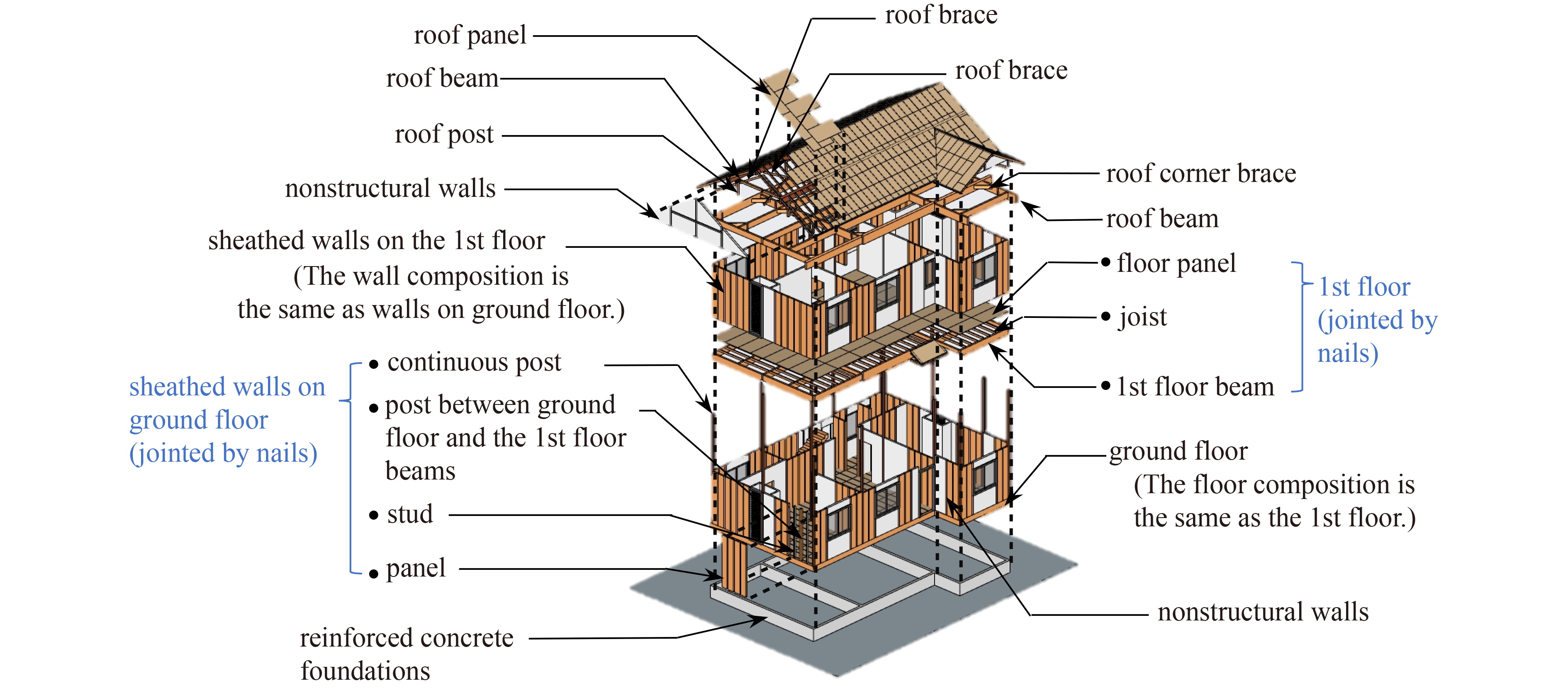
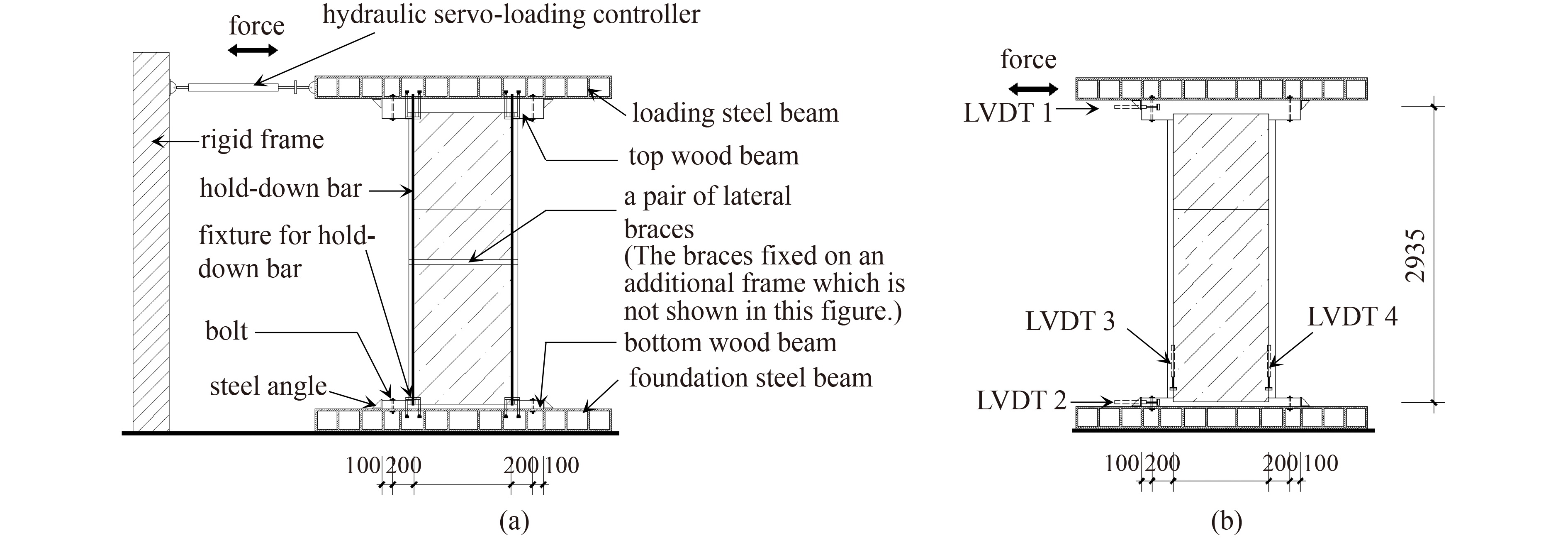
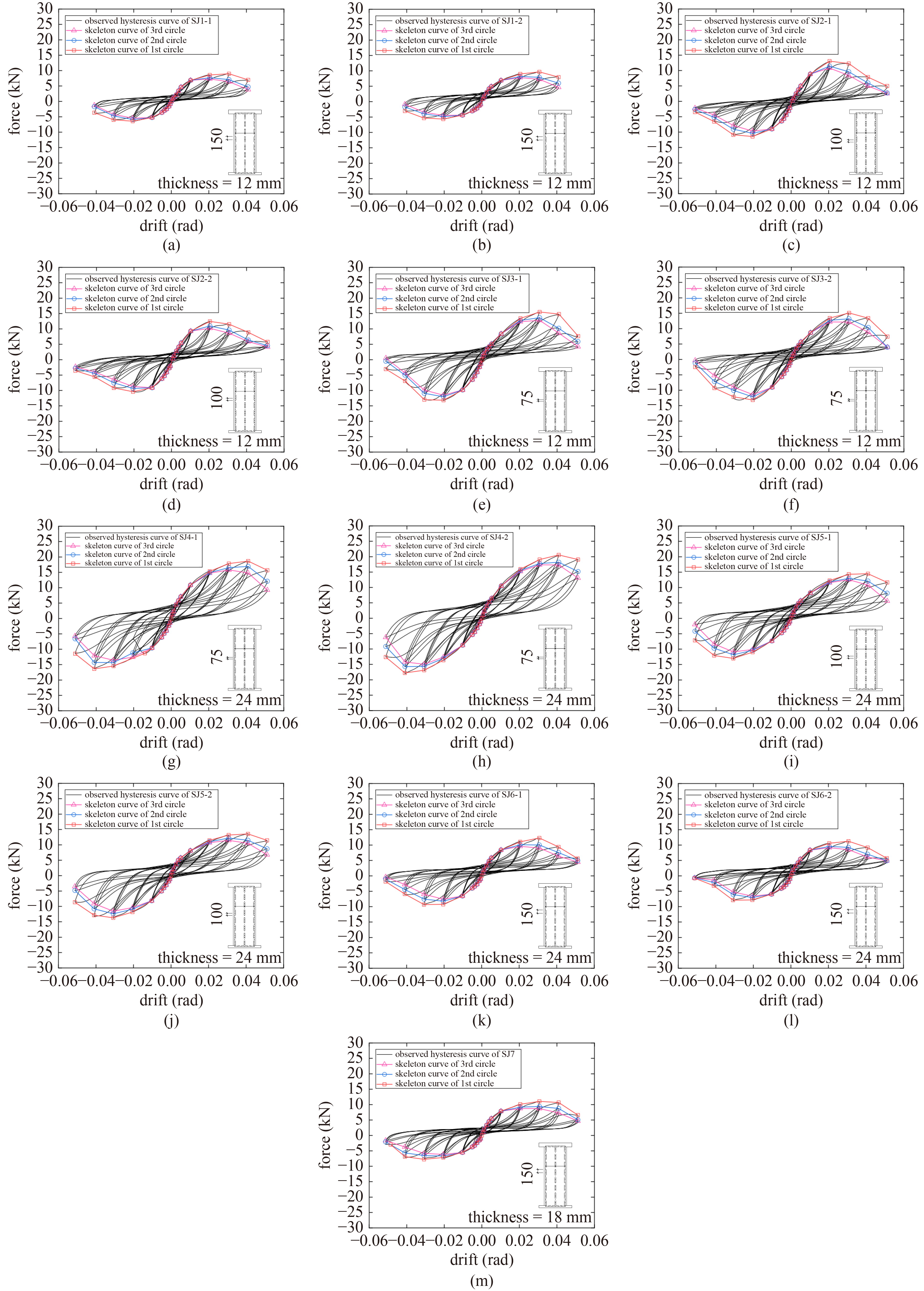
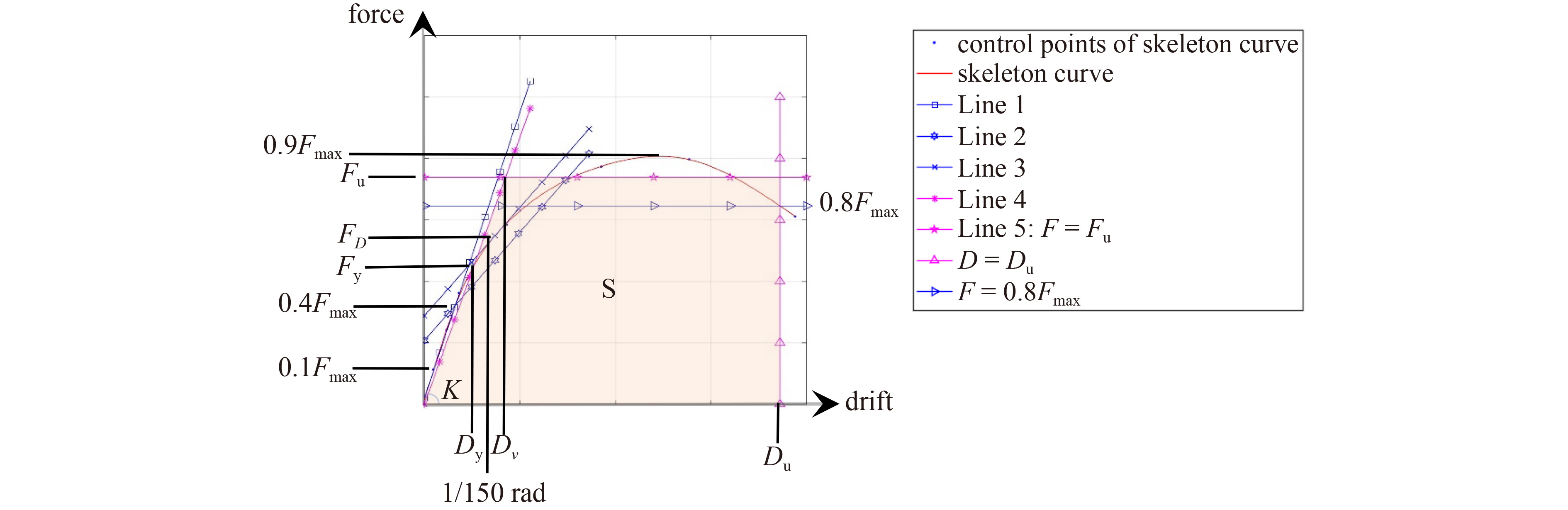
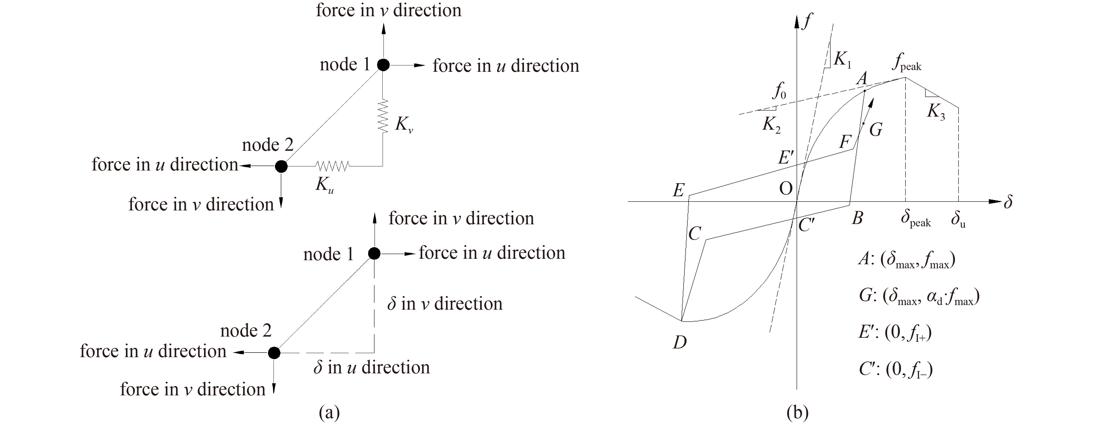
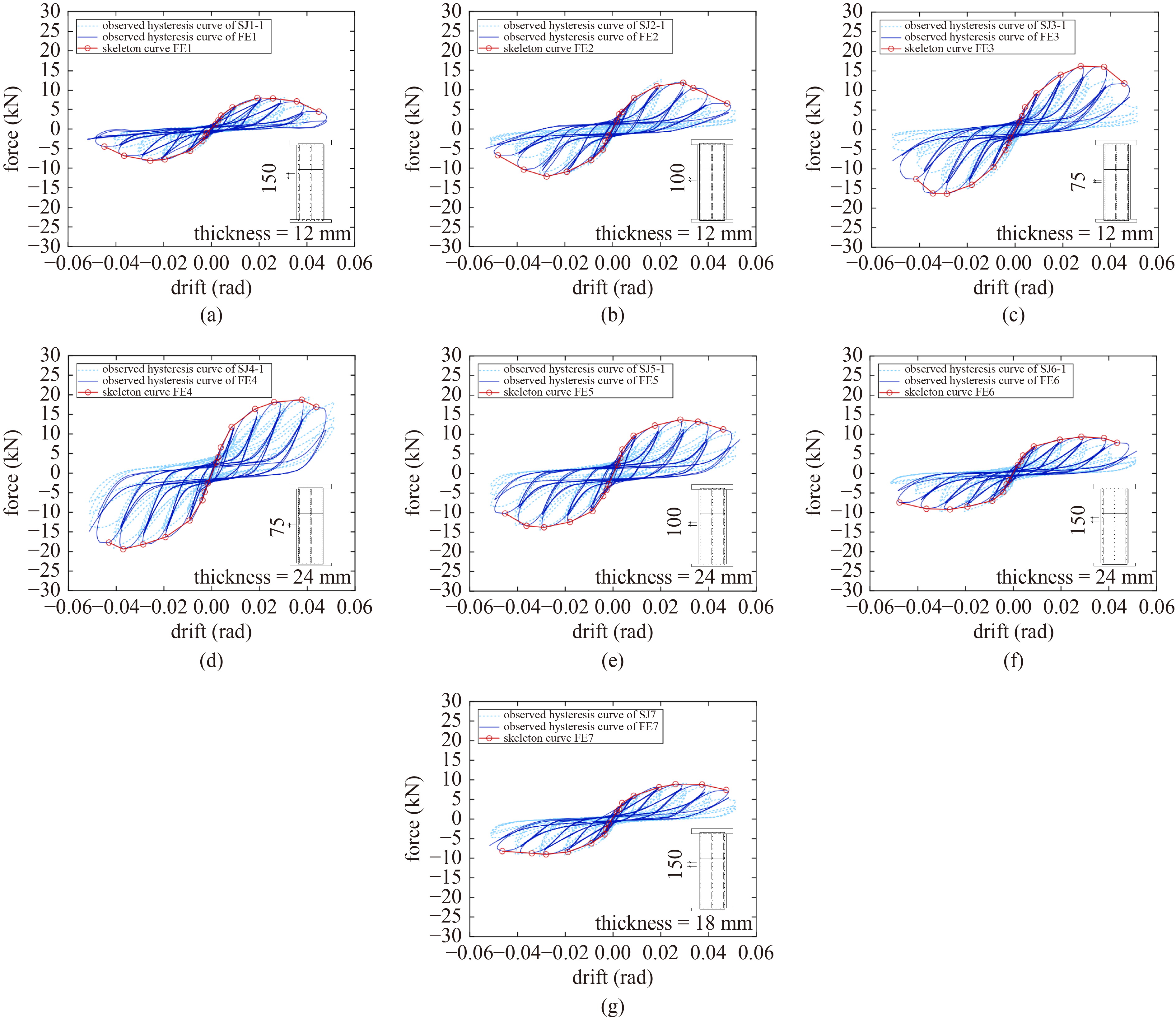
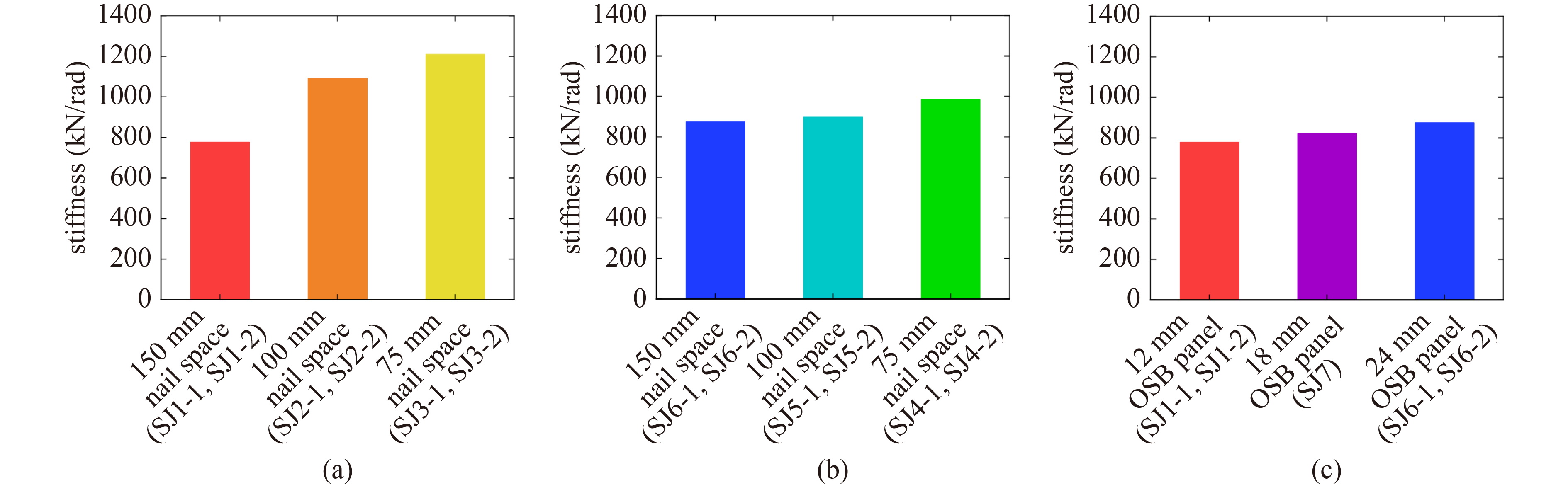
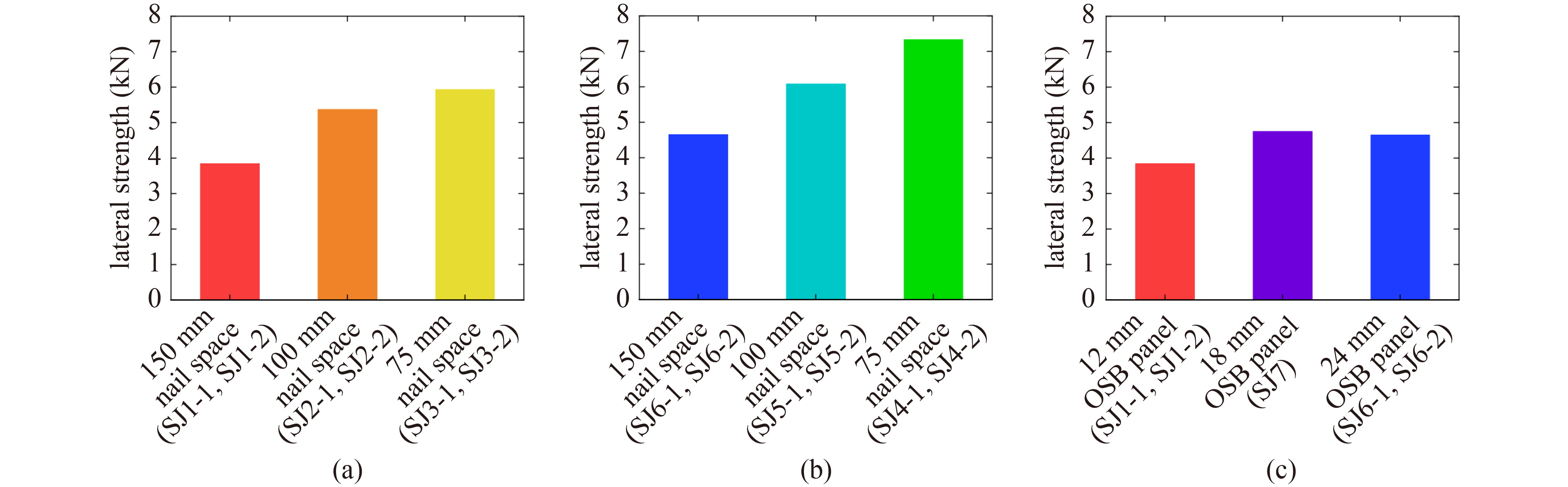
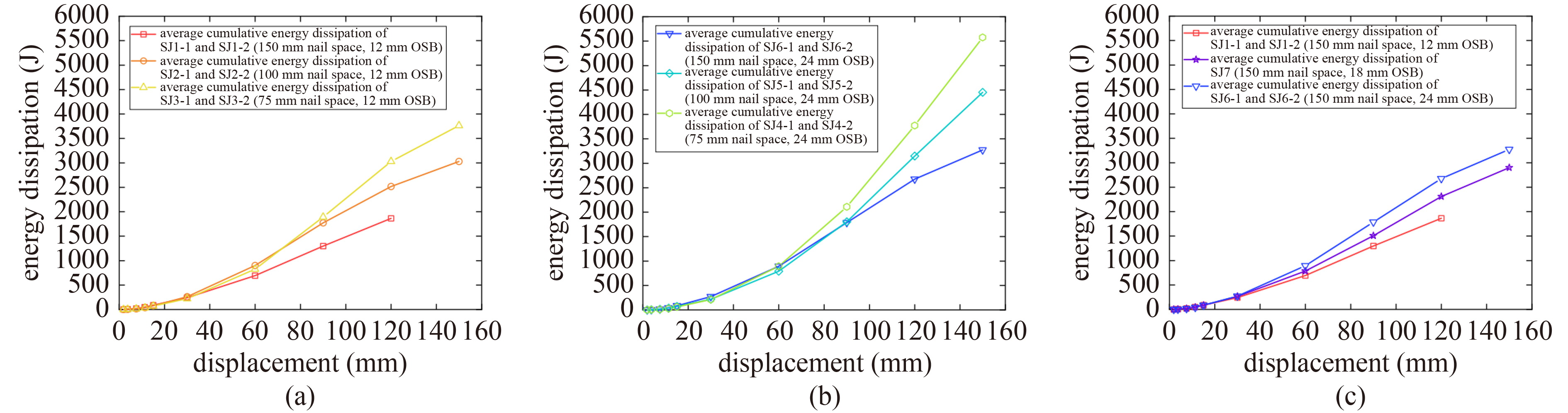
Abstract

Sheathed post-and-beam wooden structures are distinct from light-wood structures. They allow for using sheathing panels that are smaller (0.91 m × 1.82 m) than standard-sized panels (1.22 m × 2.44 m or 2.44 m × 2.44 m). Evidence indicates that nail spacing and panel thickness determine the lateral capacity of the wood frame shear walls. To verify the lateral shear performance of wood frame shear walls with smaller panels, we subjected 13 shear walls, measuring 0.91 m in width and 2.925 m in height, to a low-cycle cyclic loading test with three kinds of nail spacing and three panel thicknesses. A nonlinear numerical simulation analysis of the wall was conducted using ABAQUS finite element (FE) software, where a custom nonlinear spring element was used to simulate the sheathing-frame connection. The results indicate that the hysteretic performance of the walls was mainly determined by the hysteretic performance of the sheathing-frame connection. When same nail specifications were adopted, the stiffness and bearing capacity of the walls were inversely related to the nail spacing and directly related to the panel thickness. The shear wall remained in the elastic stage when the drift was 1/250 rad and ductility coefficients were all greater than 2.5, which satisfied the deformation requirements of residential structures. Based on the test and FE analysis results, the shear strength of the post-and-beam wooden structures with sheathed walls was determined.

Keywords post-and-beam wooden structures with sheathed walls      low reversed cyclic loading      bearing capacity      stiffness      numerical simulation     
Corresponding Author(s): Yifeng LIU   
Just Accepted Date: 19 April 2023   Online First Date: 11 September 2023    Issue Date: 20 September 2023
 Cite this article:   
Weiguo LONG,Wenfan LU,Yifeng LIU, et al. Lateral shear performance of sheathed post-and-beam wooden structures with small panels[J]. Front. Struct. Civ. Eng., 2023, 17(7): 1117-1131.
 URL:  
https://academic.hep.com.cn/fsce/EN/10.1007/s11709-023-0939-0
https://academic.hep.com.cn/fsce/EN/Y2023/V17/I7/1117
Fig.1  System diagram of post-and-beam wooden structures with sheathed walls and a shedding floor.
Fig.2  Skeleton comparison between post-and-beam wooden structures with sheathed walls and other wooden structure systems: (a) a shear wall skeleton in the system of post-and-beam wooden structures with sheathed walls; (b) a shear wall skeleton in light wood frame constructions; (c) beam−column wood construction.
item post-and-beam wooden structures with sheathed walls modern light wood frame construction traditional beam−column wood construction
perpendicular bearing members a frame formed by posts (including continuous posts, and posts between beams) and beams studs beam−column frame
lateral resistance sheathed walls with a wooden skeleton comprising posts, beams, and studs shear wall with light wood frame beam−column frame with braces
floor system it can be matched with multiple floor forms such as heavy wood floors and light wood floors wood joisted floors multiple floor forms
roof system multiple roof systems roof truss that occupy indoor space multiple roof systems
construction and installation sheathed wood frame shear walls provide lateral resistance. the construction quality of a single nail has little effect overall, and the fault tolerance rate is high shear walls with light wood frames provide lateral resistance. the construction quality of a single nail has little effect overall, and the fault tolerance rate is high braces provide lateral resistance. therefore, the construction fault tolerance of connections is low
member section the section sizes of members are between members of traditional beam−column wood construction and modern light wood frame construction members have small-sectional sawn lumber with a width of 2 in (38 mm) large member sections and columns usually protrude more from the wall
Tab.1  Comparison between post-and-beam wooden structures with sheathed walls and other wooden structure systems
member section size (mm × mm)
post 105 × 105
top beam 105 × 180
bottom beam width × height 105 × 105
stud 45 × 105
upper panel 910 × 910
lower panel 910 × 1820
Tab.2  Frame and panel size
Fig.3  The structure of specimens: (a) specimen; (b) detail 1; (c) detail 2 (unit: mm).
test number thickness of panel (mm) nail space (mm) nail diameter (mm)
SJ1-1 12 150 3.1
SJ1-2 12 150 3.1
SJ2-1 12 100 3.1
SJ2-2 12 100 3.1
SJ3-1 12 75 3.1
SJ3-2 12 75 3.1
SJ4-1 24 75 3.1
SJ4-2 24 75 3.1
SJ5-1 24 100 3.1
SJ5-2 24 100 3.1
SJ6-1 24 150 3.1
SJ6-2 24 150 3.1
SJ7 18 150 3.1
Tab.3  Specimen number and geometric parameters
material property value
compression parallel to grain, fc (N/mm) 21.7
tension parallel to grain, ft (N/mm) 18.9
design value in bending, fm (N/mm) 20.4
longitudinal shear, fv (N/mm) 3.0
compression perpendicular, fc,90 (N/mm) 6
elastic modulus, E (N/mm2) 9500
Tab.4  Material properties of posts and beams
Fig.4  (a) Test setup; (b) measuring points arrangement.
Fig.5  Failure phenomena: (a) corn tear failure; (b) post feet pulled up; (c) nails pulled out of the panel; (d) edge tear failure; (e) nail near the panel gap sank into the panel; (f) slippage of panels; (g) panels separated from the frame; (h) nail fractured; (i) nail at the panel corner sank into the panel; (j) panel visibly warped; (k) stud foot uplift.
Fig.6  Hysteresis curves and skeleton curves of specimens: (a) SJ1-1; (b) SJ1-2; (c) SJ2-1; (d) SJ2-2; (e) SJ3-1; (f) SJ3-2; (g) SJ4-1; (h) SJ4-2; (i) SJ5-1; (j) SJ5-2; (k) SJ6-1; (l) SJ6-2; (m) SJ7.
Fig.7  Perfect bilinear approximation.
No. loading direction Ka) (kN/rad) Fya) (kN) Fua) (kN) μa) Fμa) (kN) 2/3Fmaxa) (kN) FD = 1/150 rada) (kN) K0 (kN/rad) F0b) (kN) K0,AVGc) (kN/rad) F0,AVGd) (kN)
SJ1-1 + 819.15 5.57 8.32 3.93 4.36 9.08 6.05 785.82 3.85 777.69 3.84
752.50 3.34 5.96 4.43 3.34 6.47 4.32
AVGe) 785.82 4.45 7.14 4.18 3.85 7.78 5.18
SJ1-2 + 913.76 5.28 8.75 4.28 4.81 9.72 6.48 769.55 3.82
625.34 2.89 5.22 4.16 2.83 5.75 3.83
AVGe) 769.55 4.08 6.99 4.22 3.82 7.74 5.16
SJ2-1 + 1081.86 7.48 13.17 2.89 5.75 14.32 9.55 1068.35 5.35 1092.85 5.37
1054.85 5.64 9.73 3.74 4.95 10.69 7.13
AVGe) 1068.35 6.56 11.45 3.31 5.35 12.50 8.34
SJ2-2 + 1182.50 7.18 12.36 3.59 6.15 13.41 8.94 1117.34 5.39
1052.18 4.99 8.92 3.88 4.64 9.56 6.37
AVGe) 1117.34 6.09 10.64 3.74 5.39 11.48 7.66
SJ3-1 + 1127.11 8.48 14.73 2.49 5.88 15.82 10.55 1259.13 5.90 1209.73 5.93
1391.15 7.29 12.53 3.29 5.92 13.80 5.92
AVGe) 1259.13 7.89 13.63 2.89 5.90 14.81 8.23
SJ3-2 + 1181.71 6.98 13.65 3.15 6.28 15.11 10.07 1160.34 5.96
1138.97 6.48 12.05 3.23 5.63 13.27 8.85
AVGe) 1160.34 6.73 12.85 3.19 5.96 14.19 9.46
SJ4-1 + 1141.14 9.84 16.94 3.45 8.24 18.77 12.51 1053.04 7.53 985.32 7.33
964.94 9.18 14.87 3.13 6.82 16.61 11.07
AVGe) 1053.04 9.51 15.91 3.29 7.53 17.69 11.79
SJ4-2 + 1001.26 10.94 18.91 2.71 7.96 20.54 13.70 917.60 7.13
833.93 9.17 16.27 2.48 6.47 18.08 12.05
AVGe) 917.60 10.05 17.59 2.59 7.21 19.31 12.87
SJ5-1 + 963.02 6.95 13.14 3.73 6.68 14.74 9.83 871.57 5.97 899 6.08
780.11 6.44 11.84 2.96 5.25 13.15 8.77
AVGe) 871.57 6.70 12.49 3.35 5.97 13.94 9.30
SJ5-2 + 1017.58 6.56 12.17 4.28 6.69 13.69 9.13 926.44 6.20
835.30 7.38 12.60 3.06 5.70 13.79 9.20
AVGe) 926.44 6.97 12.39 3.67 6.20 13.74 9.16
SJ6-1 + 1031.43 6.71 11.00 3.72 5.59 12.36 8.24 874.06 4.75 874.19 4.65
716.70 5.06 8.98 2.88 3.92 9.72 6.48
AVGe) 874.06 5.88 9.99 3.30 4.75 11.04 7.36
SJ6-2 + 975.08 6.53 10.41 3.87 5.40 11.32 7.54 874.31 4.54
773.55 4.35 7.52 3.49 3.68 8.40 5.60
AVGe) 874.31 5.44 8.97 3.68 4.54 9.86 6.57
SJ7 + 971.46 6.32 10.25 4.36 5.70 11.25 7.50 821.42 4.75 821.42 4.75
671.38 4.27 7.19 3.97 3.79 7.85 5.23
AVGe) 821.42 5.30 8.72 4.17 4.75 9.55 6.37
Tab.5  Target values of the skeleton curve and the average stiffness and strength values of different types of specimens
No. F0,unit (kN/m) Kunit (kN·rad−1·m−1)
SJ1-1 & SJ1-2 4.2 854.6
SJ2-1 & SJ2-2 5.9 1200.9
SJ3-1 & SJ3-2 6.5 1329.3
SJ4-1 & SJ4-2 8.0 1082.7
SJ5-1 & SJ5-2 6.6 987.9
SJ6-1 & SJ6-2 5.1 960.6
SJ7 5.2 902.6
Tab.6  Strength and stiffness of unit length wall: F0,unit and Kunit
Fig.8  User elements for sheathing-frame connection in the FE models: (a) model configuration; (b) hysteretic model.
panel thickness of the sheathing-frame connection (mm) f0 K1 K2 K3 δpeak δu h1 h2 h3 h4 h5
12 796 750 65.0 −35 7.0 14 50 0.15 0.8 0.8 0.7
18 1069 796 36.9 −40 9.3 25 50 0.10 0.8 0.8 0.7
24 978 899 51.0 −55 9.3 30 25 0.13 0.9 0.9 0.7
Tab.7  Parameters of sheathing-frame connections
Fig.9  Deformation diagram under lateral force of walls with 12 mm OSB and 75 mm nail space: (a) deformation of FE model 3, where the circled number 1 shows the local enlarged view; (b) deformation of SJ3-1.
No. Kunit (kN·rad−1·m−1) F0,unit (kN/m)
experiment numerical error experiment numerical error
FE1 854.6 781.1 −9% 4.2 4.1 −3%
FE2 1200.9 1089.7 −9% 5.9 5.8 −2%
FE3 1329.3 1200.4 −10% 6.5 7.4 14%
FE4 1082.7 1195.8 10% 8.0 8.1 1%
FE5 987.9 1011.2 2% 6.6 6.5 −1%
FE6 960.6 996.4 4% 5.1 5.6 9%
FE7 902.6 845.9 −6% 5.2 5.0 −4%
Tab.8  Comparison of test and simulation results
Fig.10  Comparison between the hysteresis curves of test and numerical simulation: (a) SJ1-1; (b) SJ2-1; (c) SJ3-1; (d) SJ4-1; (e) SJ5-1; (f) SJ6-1; (g) SJ7.
Fig.11  Comparison of the cumulative energy dissipation between the test and numerical simulation: (a) FE1; (b) FE2; (c) FE3; (d) FE4; (e) FE5; (f) FE6; (g) FE7.
Fig.12  Stiffness comparison of sheathed walls with: (a) 12 mm OSB panel and different nail space; (b) 24 mm OSB panel and different nail space; (c) 150 mm nail space and different thickness panels.
ultimate load SJ1-1 SJ1-2 SJ2-1 SJ2-2 SJ3-1 SJ3-2 SJ4-1 SJ4-2 SJ5-1 SJ5-2 SJ6-1 SJ6-2 SJ7
Fmax1,positive (kN) 9.08 9.72 14.32 13.41 15.82 15.11 18.77 20.54 14.74 13.69 12.36 11.32 11.06
Fmax1,negative (kN) 6.47 5.75 10.69 9.56 13.80 13.27 16.61 18.08 13.15 13.79 9.72 8.40 7.77
Fmax1,AVG (kN) 7.78 7.74 12.50 11.48 14.81 14.19 17.69 19.31 13.94 13.74 11.04 9.86 9.42
Fmax3,positive (kN) 7.28 7.82 10.80 10.21 12.42 12.05 15.94 17.55 12.74 11.57 9.75 9.39 8.73
Fmax3,negative (kN) 5.43 4.44 9.65 9.11 11.90 11.56 13.38 14.76 10.68 11.45 7.42 6.38 6.17
Fmax3,AVG (kN) 6.34 6.13 10.23 9.66 12.16 11.81 14.66 16.16 11.71 11.51 8.59 7.89 7.45
Fmax3,AVG/Fmax1,AVG 0.81 0.79 0.81 0.84 0.82 0.83 0.82 0.83 0.84 0.84 0.78 0.80 0.85
Tab.9  Comparison between the ultimate load of specimens under three-cycle loading
Fig.13  Lateral strength comparison between the sheathed walls with: (a) 12 mm OSB panels and different nail space; (b) 24 mm OSB panels and different nail space; (c) 150 mm nail space and different thickness panels.
Fig.14  The cumulative energy dissipation of walls with: (a) 12 mm OSB panels and different nail space; (b) 24 mm OSB panels and different nail space; (c) 150 mm nail space and different thickness panels.
1 N Kawai. Permissible Stress Method for Wooden Houses Using Post-Beam Construction. 4th ed. Tokyo: Japan Housing and Wood Technology Center, 2008 (in Japanese)
2 B Källsner, U A Girhammar. Plastic models for analysis of fully anchored light-frame timber shear walls. Engineering Structures, 2009, 31(9): 2171–2181
https://doi.org/10.1016/j.engstruct.2009.03.023
3 J W van de Lindt. Evolution of wood shear wall testing, modeling, and reliability analysis: Bibliography. Practice Periodical on Structural Design and Construction, 2004, 9(1): 44–53
https://doi.org/10.1061/(ASCE)1084-0680(2004)9:1(44
4 D Ugalde, J L Almazán, María H Santa, P Guindos. Seismic protection technologies for timber structures: A review. European Journal of Wood and Wood Products, 2019, 77(2): 173–194
https://doi.org/10.1007/s00107-019-01389-9
5 50005-2017 GB. Standard for Design of Timber Structures. Beijing: China Architecture & Building Press, 2017 (in Chinese)
6 E N Anderson, R J Leichti, E G Sutt, D V Rosowsky. Sheathing nail bending-yield stress: Effect on cyclic performance of wood shear walls. Wood and Fiber Science, 2007, 39(4): 536–547
7 A Demir, C Demirkir, I Aydin. The effects of wood species, nail size, grain direction and layer numbers on lateral nail strength of structural plywood panels. Sigma Journal of Engineering and Natural Sciences, 2020, 11(2): 141–148
8 N Nishiyama, N Ando. Analysis of load-slip characteristics of nailed wood joints: Application of a two-dimensional geometric nonlinear analysis. Journal of Wood Science, 2003, 49(6): 505–512
https://doi.org/10.1007/s10086-003-0519-9
9 T Sartori, R Tomasi. Experimental investigation on sheathing-to-framing connections in wood shear walls. Engineering Structures, 2013, 56: 2197–2205
https://doi.org/10.1016/j.engstruct.2013.08.039
10 E2126-09 ASTM. Standard Test Methods for Cyclic (Reversed) Load Test for Shear Resistance of Vertical Elements of the Lateral Force Resisting Systems for Buildings. West Conshohocken, PA: ASTM, 2009
11 16670 ISO. Timber Structure-Joint Made with Mechanical Fasters-Quasi-Static Reversed Cyclic Test Method. Geneva: ISO, 2003
12 P K Dean, H W Shenton. Experimental investigation of the effect of vertical load on the capacity of wood shear walls. Journal of Structural Engineering, 2005, 131(7): 1104–1113
https://doi.org/10.1061/(ASCE)0733-9445(2005)131:7(1104
13 F Guíñez, María H Santa, J L Almazán. Monotonic and cyclic behaviour of wood frame shear walls for mid-height timber buildings. Engineering Structures, 2019, 189: 100–110
https://doi.org/10.1016/j.engstruct.2019.03.043
14 C M Uang, K Gatto. Effects of finish materials and dynamic loading on the cyclic response of wood frame shear walls. Journal of Structural Engineering, 2003, 129(10): 1394–1402
https://doi.org/10.1061/(ASCE)0733-9445(2003)129:10(1394
15 Institute of Japan (AIJ) Architectural. Standard for Structural Design of Timber Structures. Tokyo: Architectural Institute of Japan, 2006 (in Japanese)
16 G Wu. Light wood frame construction utilizing small-diameter round timber and investigation of the structural behaviour. Dissertation for the Doctoral Degree. Harbin: Harbin Institute of Technology, 2015 (in Chinese)
17 B Folz, A Filiatrault. Cyclic analysis of wood shear walls. Journal of Structural Engineering, 2001, 127(4): 433–441
https://doi.org/10.1061/(ASCE)0733-9445(2001)127:4(433
18 D1761-20 ASTM. Standard Test Methods for Mechanical Fasteners in Wood. West Conshohocken, PA: ASTM, 2000
19 H ChengC NiX Lv. Performance of perforated wood-frame shear walls with transverse walls and vertical load. China Civil Engineering Journal, 2006, 39(12): 33−47 (in Chinese)
20 Emergency Management Agency (FEMA) Federal. Pre-standard and Commentary for the Seismic Rehabilitation of Buildings, FEMA 356. Washington, D.C.: FEMA, 2000
[1] Pengfei LI, Ziqi JIA, Mingju ZHANG, Xiaojing GAO, Haifeng WANG, Wu FENG. Bending failure performance of a shield tunnel segment based on full-scale test and numerical analysis[J]. Front. Struct. Civ. Eng., 2023, 17(7): 1033-1046.
[2] Dongning SUN, Baoning HONG, Xin LIU, Ke SHENG, Guisen WANG, Zhiwei SHAO, Yunlong YAO. Numerically investigating the crushing of sandstone by a tooth hob[J]. Front. Struct. Civ. Eng., 2023, 17(6): 964-979.
[3] Hua-Fei HE, Zhao-Ping LI, Shao-Lin MA, Xiang-Yang CUI. Effect of strata restraint on seismic performance of prefabricated sidewall joints in fabricated subway stations[J]. Front. Struct. Civ. Eng., 2023, 17(5): 763-779.
[4] Ramin VALI, Saeed KHOSRAVI, Majid BEYGI. Undrained seismic bearing capacity of strip footing adjacent to a heterogeneous excavation[J]. Front. Struct. Civ. Eng., 2023, 17(4): 566-583.
[5] Wenchang SUN, Nan JIANG, Chuanbo ZHOU, Jinshan SUN, Tingyao WU. Safety assessment for buried drainage box culvert under influence of underground connected aisle blasting: A case study[J]. Front. Struct. Civ. Eng., 2023, 17(2): 191-204.
[6] Sahand KHALILZADEHTABRIZI, Hamed SADAGHIAN, Masood FARZAM. Uncertainty of concrete strength in shear and flexural behavior of beams using lattice modeling[J]. Front. Struct. Civ. Eng., 2023, 17(2): 306-325.
[7] Pong-in INTARIT, Kanin TARNTIRA, Teerapong SENJUNTICHAI, Suraparb KEAWSAWASVONG. Axisymmetric loading on nanoscale multilayered media[J]. Front. Struct. Civ. Eng., 2023, 17(1): 152-164.
[8] Yusheng YANG, Haitao YU, Yong YUAN, Dechun LU, Qiangbing HUANG. A numerical framework for underground structures in layered ground under inclined P-SV waves using stiffness matrix and domain reduction methods[J]. Front. Struct. Civ. Eng., 2023, 17(1): 10-24.
[9] Yue CHEN, Rong XU, Hao WU, Tao SHENG. A multi-objective design method for seismic retrofitting of existing reinforced concrete frames using pin-supported rocking walls[J]. Front. Struct. Civ. Eng., 2022, 16(9): 1089-1103.
[10] Senping WANG, Xiaolong LIU, Bo YUAN, Minjie SHI, Yanhui WEI. Out-of-plane elastic buckling load and strength design of space truss arch with a rectangular section[J]. Front. Struct. Civ. Eng., 2022, 16(9): 1141-1152.
[11] Jiaxin HE, Shaohui HE, Xiabing LIU, Jinlei ZHENG. Structural design and mechanical responses of closely spaced super-span double tunnels in strongly weathered tuff strata[J]. Front. Struct. Civ. Eng., 2022, 16(6): 685-703.
[12] Jingcai ZHANG, Yong DING, Xinchun GUAN. Study of the mechanics of progressive collapse of FPB isolated beam-pier substructures[J]. Front. Struct. Civ. Eng., 2022, 16(6): 718-728.
[13] Yixian LI, Limin SUN, Wang ZHU, Wei ZHANG. A dynamic stiffness-based framework for harmonic input estimation and response reconstruction considering damage[J]. Front. Struct. Civ. Eng., 2022, 16(4): 448-460.
[14] Huailei CHENG, Liping LIU, Lijun SUN. Bridging the gap between laboratory and field moduli of asphalt layer for pavement design and assessment: A comprehensive loading frequency-based approach[J]. Front. Struct. Civ. Eng., 2022, 16(3): 267-280.
[15] Shuvankar DAS, Debarghya CHAKRABORTY. Effect of interface adhesion factor on the bearing capacity of strip footing placed on cohesive soil overlying rock mass[J]. Front. Struct. Civ. Eng., 2021, 15(6): 1494-1503.
Viewed
Full text


Abstract

Cited

  Shared   
  Discussed