|
|
|
Finite element analysis of stress concentrations and failure criteria in composite plates with circular holes |
Abdelhak KHECHAI1,*( ),Abdelouahab TATI2,Abdelhamid GUETTALA1 ),Abdelouahab TATI2,Abdelhamid GUETTALA1 |
1. Laboratory of Civil Engineering, University of Biskra, Biskra 07000, Algeria
2. Laboratory of Energy Engineering and Materials, University of Biskra, Biskra 07000, Algeria |
|
|
|
|
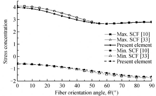
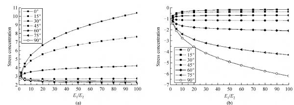
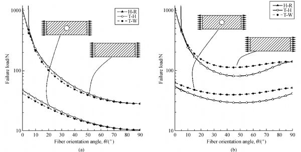
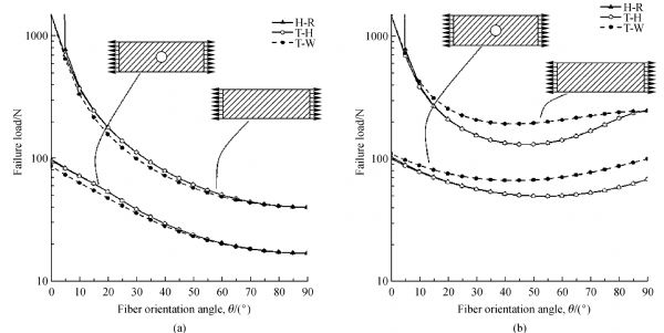
Abstract In this study, the stress concentration factors (SCF) in cross-and-angle-ply laminated composite plates as well as in isotropic plates with single circular holes subjected to uniaxial loading is studied. A quadrilateral finite element of four-node with 32 degrees of freedom at each node, previously developed for the bending and mechanical buckling of laminated composite plates, is used to evaluate the stress distribution in laminated composite plates with central circular holes. Based up on the classical plate theory, the present finite element is a combination of a linear isoparametric membrane element and a high precision rectangular Hermitian element. The numerical results obtained by the present element compare favorably with those obtained by the analytic approaches published in literature. It is observed that the obtained results are very close to the reference results, which demonstrates the accuracy of the present element. Additionally, to determine the first ply failure (FPF) of laminated plate, several failure criterions are employed. Finally, to show the effect of E1/E2 ratio on the failure of plates, a number of figures are given for different fiber orientation angles.
|
| Keywords
laminated composite plates
stress concentration
geometric singularity
anisotropic effect
|
|
Corresponding Author(s):
Abdelhak KHECHAI
|
|
Online First Date: 09 September 2014
Issue Date: 10 October 2014
|
|
| 1 |
Aluko O, Whitworth H. Analysis of stress distribution around pin loaded holes in orthotropic plates. Composite Structures, 2008, 86(4): 308–313
https://doi.org/10.1016/j.compstruct.2008.06.001
|
| 2 |
Topal U, Uzman ü. Frequency optimization of laminated composite angle-ply plates with circular hole. Materials & Design, 2008, 29(8): 1512–1517
https://doi.org/10.1016/j.matdes.2008.03.002
|
| 3 |
Sheng H, Ye J. A state space finite element for laminated composite plates. Computer Methods in Applied Mechanics and Engineering, 2002, 191(37–38): 4259–4276
https://doi.org/10.1016/S0045-7825(02)00379-1
|
| 4 |
Ukadgaonker V, Rao D. A general solution for moments around holes in symmetric laminates. Composite Structures, 2000, 49(1): 41–54
https://doi.org/10.1016/S0263-8223(99)00124-5
|
| 5 |
Ghezzo F, Giannini G, Cesari F, Caligiana G. Numerical and experimental analysis of the interaction between two notches in carbon fibre laminates. Composites Science and Technology, 2008, 68(3–4): 1057–1072
https://doi.org/10.1016/j.compscitech.2007.07.023
|
| 6 |
Louhghalam A, Igusa T, Park C, Choi S, Kim K. Analysis of stress concentrations in plates with rectangular openings by a combined conformal mapping—finite element approach. International Journal of Solids and Structures, 2011, 48(13): 1991–2004
https://doi.org/10.1016/j.ijsolstr.2011.03.005
|
| 7 |
Dharmin P, Khushbu P, Chetan J. A review on stress analysis of an infinite plate with cut-outs. International Journal of Scientific and Research Publications, 2012, 2(11): 1–7
|
| 8 |
Peterson R E, Plunkett R. Stress concentration factors. Journal of Applied Mechanics, 1975, 42(1): 248
https://doi.org/10.1115/1.3423544
|
| 9 |
Nagpal S, Jain N, Sanyal S. Stress concentration and its mitigation techniques in flat plate with singularities—a critical review. Engineering Journal, 2012, 16(1): 1–16
|
| 10 |
Kaltakci M Y. Stress concentrations and failure criteria in anisotropic plates with circular holes subjected to tension or compression. Computers & Structures, 1996, 61(1): 67–78
https://doi.org/10.1016/0045-7949(96)00009-0
|
| 11 |
Green A, Zerna W. Theoretical Elasticity. Oxford: The Clarendon Press, 1954
|
| 12 |
Hearmon R F S. An Introduction to Applied Anisotropic Elasticity. Oxford: The Clarendo Press, 1961
|
| 13 |
Lekhnitskii S G. Theory of Elasticity of an Anisotropic Elastic Body. San Francisco: Holden-Day, Inc., 1963
|
| 14 |
Savin G N. Stress Distribution around Holes. NASA TT-607. 1970
|
| 15 |
Arslan H M, Kaltakci M Y, Yerli H R. Effect of circular holes on cross-ply laminated composite plates. The Arabian Journal for Science & Engineering, 2009, 34(2B): 301–305
|
| 16 |
Yang Y, Liu J, Cai C W. Analytical solutions to stress concentration problem in plates containing rectangular hole under biaxial tensions. Acta Mechanica Solida Sinica, 2008, 21(5): 411–419
https://doi.org/10.1007/s10338-008-0850-1
|
| 17 |
Muskhelishvili N I. Some Basic Problems of the Mathematical Theory of Elasticity. New York: Springer Science & Business Media, 1977
|
| 18 |
England A H. Complex Variable Methods in Elasticity. New York: Wiley-Interscience, 1971
|
| 19 |
Milne-Thomson L M. Plane Elastic Systems. Vol 6. Berlin: Springer-Verlag, 1960
|
| 20 |
Savin G N. Stress Concentration around Holes. Vol 1. New York: Pergamon Press, 1961
|
| 21 |
Lekhnitskii S. Anisotropic Plates. Translated from the second Russian edition by Tsai S W, Cheron T. New York: Gordon and Breach Science Publishers Inc., 1968
|
| 22 |
Ukadgaonker V, Rao D. A general solution for stress resultants and moments around holes in unsymmetric laminates. Composite Structures, 2000, 49(1): 27–39
https://doi.org/10.1016/S0263-8223(99)00123-3
|
| 23 |
Xu X W, Sun L X, Fan X Q. Stress concentration of finite composite laminates with elliptical hole. Computers & Structures, 1995, 57(1): 29–34
https://doi.org/10.1016/0045-7949(94)00588-T
|
| 24 |
Wu X, Cheng S. A higher-order theory for plane stress conditions of laminates consisting of isotropic layers. Journal of Applied Mechanics, 1999, 66(1): 95–100
https://doi.org/10.1115/1.2789174
|
| 25 |
Chen C H, Hsu J. The stress intensity factors of slightly undulating interface cracks of bimaterials. International Journal of Fracture, 1996, 80(4): 277–293
https://doi.org/10.1007/BF00018508
|
| 26 |
Bryukhanova E N. Thermal stresses in a circular cylinder with regularly arranged circular cavities. International Applied Mechanics, 1969, 5(4): 380–384
|
| 27 |
Wang X F, Hasebe N. Bending of a thin plate containing a rigid inclusion and a crack. Engineering Analysis with Boundary Elements, 2000, 24(2): 145–153
https://doi.org/10.1016/S0955-7997(99)00062-4
|
| 28 |
Tsukrov I, Novak J. Effective elastic properties of solids with defects of irregular shapes. International Journal of Solids and Structures, 2002, 39(6): 1539–1555
https://doi.org/10.1016/S0020-7683(01)00285-2
|
| 29 |
Datsyshin A P, Marchenko G P. Interaction of curvilinear cracks with the boundary of an elastic half-plane. Soviet Materials Science, 1984, 20(5): 466–473
|
| 30 |
Vigdergauz S. Optimal stiffening of holes under equibiaxial tension. International Journal of Solids and Structures, 1993, 30(4): 569–577
https://doi.org/10.1016/0020-7683(93)90188-D
|
| 31 |
Exadaktylos G, Liolios P, Stavropoulou M. A semi-analytical elastic stress-displacement solution for notched circular openings in rocks. International Journal of Solids and Structures, 2003, 40(5): 1165–1187
https://doi.org/10.1016/S0020-7683(02)00646-7
|
| 32 |
Cherkaev A, Grabovsky Y, Movchan A B, Serkov S K. The cavity of the optimal shape under the shear stresses. International Journal of Solids and Structures, 1998, 35(33): 4391–4410
https://doi.org/10.1016/S0020-7683(97)00214-X
|
| 33 |
Sharma D S. Stress concentration around circular/elliptical/triangular cutouts in infinite composite plate. In: Proceedings of the World Congress onEngineering. London, 2011
|
| 34 |
Ounis H, Tati A, Benchabane A. Thermal buckling behavior of laminated composite plates: A finite-element study. Frontiers of Mechanical Engineering, 2014, 9(1): 41–49
https://doi.org/10.1007/s11465-014-0284-z
|
| 35 |
Nishioka T, Atluri S. Stress analysis of holes in angle-ply laminates: an efficient assumed stress “special-hole-element” approach and a simple estimation method. Computers & Structures, 1982, 15(2): 135–147
https://doi.org/10.1016/0045-7949(82)90061-X
|
| 36 |
Piltner R. Special finite elements with holes and internal cracks. International Journal for Numerical Methods in Engineering, 1985, 21(8): 1471–1485
https://doi.org/10.1002/nme.1620210809
|
| 37 |
Chen H C. Special finite elements including stress concentration effects of a hole. Finite Elements in Analysis and Design, 1993, 13(4): 249–258
https://doi.org/10.1016/0168-874X(93)90042-O
|
| 38 |
Pan E, Yang B, Cai G, Yuan F G. Stress analyses around holes in composite laminates using boundary element method. Engineering Analysis with Boundary Elements, 2001, 25(1): 31–40
https://doi.org/10.1016/S0955-7997(00)00066-7
|
| 39 |
Li F, He Y T, Fan C H, Li H P, Zhang H X. Investigation on three-dimensional stress concentration of LY12-CZ plate with two equal circular holes under tension. Materials Science and Engineering: A, 2008, 483–484: 474–476
https://doi.org/10.1016/j.msea.2006.08.146
|
| 40 |
Mittal N D, Jain N K. The optimize design of a square simply supported isotropic plate with central circular hole for reduction of stress concentration subjected to transverse static loading. In: Proceedings of International Conference on Theoretical, Applied, Computational and Experimental Mechanics. Kharagpur, 2007
|
| 41 |
Ukadgaonker V, Kakhandki V. Stress analysis for an orthotropic plate with an irregular shaped hole for different in-plane loading conditions—Part 1. Composite Structures, 2005, 70(3): 255–274
https://doi.org/10.1016/j.compstruct.2004.08.032
|
| 42 |
Tati A, Abibsi A. Un elementfini pour laflexion et leflambage des plaques minces stratifiees en materiaux composites. Revue des Composites et des Materiaux Avances, 2007, 17(3): 279–296 (in French)
|
| 43 |
Hashin Z. Failure criteria for unidirectional fiber composites. Journal of Applied Mechanics, 1980, 47(2): 329–334
https://doi.org/10.1115/1.3153664
|
| 44 |
Azzi V, Tsai S. Anisotropic strength of composites. Experimental Mechanics, 1965, 5(9): 283–288
https://doi.org/10.1007/BF02326292
|
| 45 |
Hahn H T, Tsai S W. Introduction to Composite Materials. Boca Raton: CRC Press, 1980
|
|
Viewed |
|
|
|
Full text
|
|
|
|
|
Abstract
|
|
|
|
|
Cited |
|
|
|
|
| |
Shared |
|
|
|
|
| |
Discussed |
|
|
|
|