|
|
|
Dynamic modeling of hydrostatic guideway considering compressibility and inertia effect |
Yikang DU1,Kuanmin MAO1,*( ),Yaming ZHU1,Fengyun WANG1,Xiaobo MAO1,Bin LI1,2 ),Yaming ZHU1,Fengyun WANG1,Xiaobo MAO1,Bin LI1,2 |
1. School of Mechanical Science and Engineering, Huazhong University of Science and Technology, Wuhan 430074, China
2. State Key Laboratory of Digital Manufacturing Equipment and Technology, Huazhong University of Science and Technology, Wuhan 430074, China |
|
|
|
|
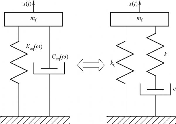
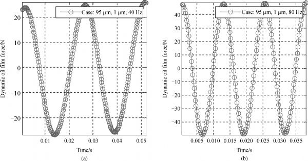
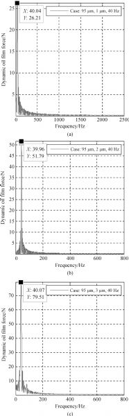
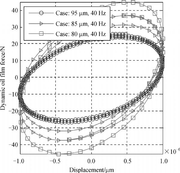
Abstract Hydrostatic guideways are used as an alternative to contact bearings due to high stiffness and high damping in heavy machine tools. To improve the dynamic characteristic of bearing structure, the dynamic modeling of the hydrostatic guidway should be accurately known. This paper presents a “mass-spring-Maxwell” model considering the effects of inertia, squeeze, compressibility and static bearing. To determine the dynamic model coefficients, numerical simulation of different cases between displacement and dynamic force of oil film are performed with fluent code. Simulation results show that hydrostatic guidway can be taken as a linear system when it is subjected to a small oscillation amplitude. Based on a dynamic model and numerical simulation, every dynamic model’s parameters are calculated by the Levenberg-Marquardt algorithm. Identification results show that “mass-spring-damper” model is the most appropriate dynamic model of the hydrostatic guidway. This paper provides a reference and preparation for the analysis of the dynamic model of the similar hydrostatic bearings.
|
| Keywords
hydrostatic guidway
dynamic model
dynamic mesh technique
Levenberg-Marquardt
mass-spring-damper model
|
|
Corresponding Author(s):
Kuanmin MAO
|
|
Online First Date: 09 March 2015
Issue Date: 01 April 2015
|
|
| 1 |
Brown G. The dynamic characteristics of a hydrostatic thrust bearing. International Journal of Machine Tool Design and Research, 1961, 1(1-2): 157–171(J)
https://doi.org/10.1016/0020-7357(61)90050-6
|
| 2 |
Dimond T W, Sheth P N, Allaire P E, Identification methods and test results for tilting pad and fixed geometry journal bearing dynamic coefficients-A review. Shock and vibration, 2009, 16(1): 13–43
https://doi.org/10.3233/SAV-2009-0452
|
| 3 |
Bouzidane A, Thomas M. Equivalent stiffness and damping investigation of a hydrostatic journal bearing. Tribology Transactions, 2007, 50(2): 257–267
https://doi.org/10.1080/10402000701309745
|
| 4 |
Jolly P, Hassini M A, Arghir M, . Identification of stiffness and damping coefficients of hydrostatic bearing with angled injection. Proceedings of the Institution of Mechanical Engineers, Part J: Journal of Engineering Tribology, 2013, 227(8): 905–911
https://doi.org/10.1177/1350650113482613
|
| 5 |
Jeon S Y, Kim K H. A fluid film model for finite element analysis of structures with linear hydrostatic bearings. Proceedings of the Institution of Mechanical Engineers, Part C: Journal of Mechanical Engineering Science, 2004, 218(3): 309–316
https://doi.org/10.1243/095440604322900435
|
| 6 |
Wang Z W, Zhao W H, Lu B H. Influencing factors on dynamic response of hydrostatic guideways. Advanced Materials Research, 2011, 418-420: 2095–2101
https://doi.org/10.4028/www.scientific.net/AMR.418-420.2095
|
| 7 |
Gao D, Zheng D, Zhang Z. Theoretical analysis and numerical simulation of the static and dynamic characteristics of hydrostatic guides based on progressive mengen flow controller. Chinese Journal of Mechanical Engineering, 2010, 23(06): 709–716
https://doi.org/10.3901/CJME.2010.06.709
|
| 8 |
Zhao J H, gao D R. Dynamic characteristic comparison of open-type hydrostatic worktable both before and after linearization. Journal of Mechanical Engineering, 2012, 48(24): 158 (in Chinese)
https://doi.org/10.3901/JME.2012.24.158
|
| 9 |
9.Lee W J, Kim S I. Joint stiffness identification of an ultra-precision machine for machining large-surface micro-features. International Journal of Precision Engineering and Manufacturing, 2009, 10(5): 115–121
https://doi.org/10.1007/s12541-009-0102-4
|
| 10 |
Huang S, Borca-Tasciuc D A, Tichy J A. A simple expression for fluid inertia force acting on micro-plates undergoing squeeze film damping. Proceedings of the Royal Society A: Mathematical, Physical and Engineering Science, 2010, 467(2126): 522–536
https://doi.org/10.1098/rspa.2010.0216
|
| 11 |
Brecher C, Baum C, Winterschladen M, . Simulation of dynamic effects on hydrostatic bearings and membrane restrictors. Production Engineering, 2007, 1(4): 415–420
https://doi.org/10.1007/s11740-007-0051-7
|
| 12 |
Hashemi S, Roylance B. Analysis of an oscillatory oil squeeze film including effects of fluid inertia. Tribology Transactions, 1989, 32(4): 461–468
https://doi.org/10.1080/10402008908981914
|
| 13 |
Hashemi S, Roylance B. Steady-state behavior of squeeze film bearings subjected to harmonic excitation—Including fluid inertia and system effects. Tribology Transactions, 1989, 32(4): 431–438
https://doi.org/10.1080/10402008908981910
|
| 14 |
Tichy J A. Measurements of squeeze-film bearing forces and pressures, including the effect of fluid inertia. ASLE Transactions, 1985, 28(4): 520–526
https://doi.org/10.1080/05698198508981650
|
| 15 |
Andres S L. Transient response of externally pressurized fluid film bearings?. Tribology Transactions, 1997, 40(1): 147–155
https://doi.org/10.1080/10402009708983640
|
| 16 |
ANSYS-FLUENT. Documentations Solver Theory/Fluent [M/OL], 2013
|
| 17 |
Bevington P R, Robinson D K. Data Reduction and Error Analysis for the Physical Sciences. New York: McGraw-Hill, 1991, 151–153
|
| 18 |
Wang G, Luo C. Data Processing of Engineering. <PublisherLocation>Cha<?Pub Caret?>ngchun</PublisherLocation>: Jilin University Press, 1990, 202–204
|
|
Viewed |
|
|
|
Full text
|
|
|
|
|
Abstract
|
|
|
|
|
Cited |
|
|
|
|
| |
Shared |
|
|
|
|
| |
Discussed |
|
|
|
|